
Since the Italian Renaissance, three-dimensional representation has been standardized in the West in a system we now know as "perspective". It depicts real objects in 3-space as geometric shapes in 2-space, and involves the use of one, two, or three "vanishing points" to guide the construction of objects. It is a consistent mapping system, and serves quite adequately for most purposes. Most people are familiar with constructions such as this one:

This model resulted in the system of perspective we all know. It seems reasonable, and we are used to it; however, there are some problems of depiction which it does not address.
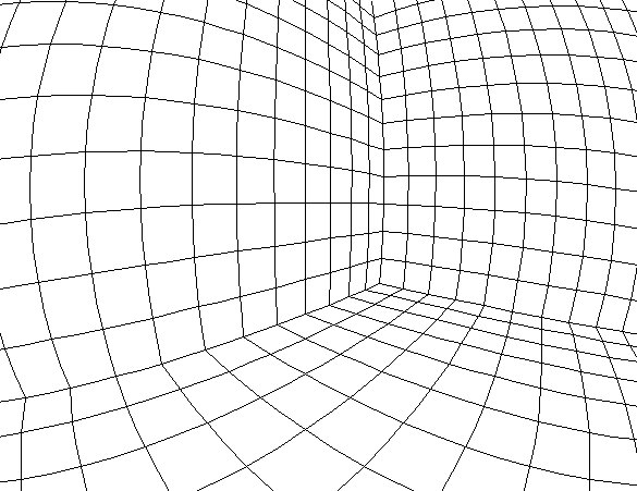
For example: suppose you are standing on the sidewalk, gazing at a wall directly across the street. Imagine that there is a street sign off to the left, and a streetlamp off to the right. The depiction of this view using standard perspective might look something like this:
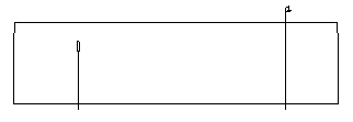
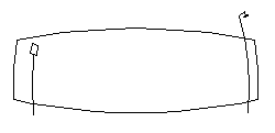
|
How might this kind of curvilinear depiction be standardized mathematically? First of all, assume the eye to be a sphere with a pinhole at one end through which light passes (the math needed to describe the path of light through a lens is much more complex, and is not really needed). Any point in 3-space in front of the eye creates a straight line through the
pinhole, intersecting the back of the eye at a single point. The collection of all such points on the retina would be a two-dimensional depiction of the scene. However, it is not on a flat surface, and, unless we want to create all our images on the inside of a hemisphere, we will require the image to be transformed into a flat one. |
|

|
There are several possible ways of doing this; the "Sight" program uses one which works like this:
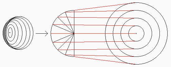
You may notice that this method will restrict the size of the image: whatever scalar multiple one uses to transform the center angle to the radius in polar co-ordinates, there is a limit to how big the image can get. Once again, this accords with common sense: the view in our eye can occupy only somewhat more than half of the inner surface of the retina. Our "mind's eye" is a circle of finite radius.
|
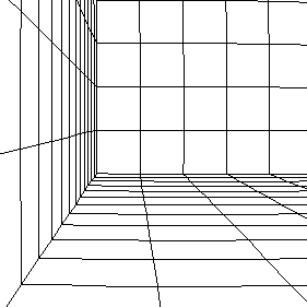
To create an algorithm to transform all the points in the scene into points on the plane, we first must know the 3-space co-ordinates of the point of view (i.e. the "pinhole") and those of the point viewed (i.e., the point in 3-space in focus for the viewer). We then rotate space to line up with an ideal axis of the eye, and, using a double matrix transformation, map each 3-D point (x, y, z) taken from the scene to a polar co-ordinate point (R, w) on the plane (See the section The Math of the "Sight" Algorithm for the mathematical details of this). If you zoom in on the resulting image, and consider only the area around the fovea at the center of vision, then the image is a close approximation of standard perspective, as you can see from the example to the right.
|
|
|
|
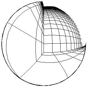
This is not unlike the relationship between classical or Newtonian space and Riemannian space: locally, Riemannian space can be considered Newtonian, and it obeys all the common-sense rules of space. But, at the scale of billions of light-years, Euclid's Fifth Postulate fails, and space curves back on itself. Similarly, when we zoom out on a "Sight" image, the curvilinear nature of the image becomes evident, as shown in the examples to the right and below. At the extreme, the outer part of the image gets squashed arbitrarily close to the limiting circle of the mind's eye, as shown in the example to the right. |
|
|
| An image drawn from an early stage of the development of "Sight" may be viewed by clicking on the link to the right. |
|
 Palace |
The Math of the "Sight" Algorithm
We begin with a point in the scene Q = (x0, y0, z0) , a point of view A = (a, b, c) , and a center of vision or point viewed D = (d, e, f).
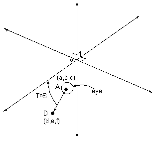 By a series of transformations we arrive at a point (R, w) in polar co-ordinates - the projected image of Q on the plane.
Then S(x0, y0, z0) = (x0- a, y0- b, z0- c).
Next we double-rotate the axis of vision to coincide with the y-axis. T = bi-rotational norm-preserving transormation taking the line passing through D and A to the y-axis.
Let t = arcsin[(f-c)/{(d-a)2+(e-b)2+(f-c)2}½]
and s = arcsin[(e-b)/{(d-a)2+(e-b)2}½] .
These are the angles of rotation.
Then T =  and P = (x, y, z) = ToS(Q) .
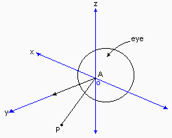 Finally, we take any shifted/rotated point P and create its image in the plane.
A = center of iris = origin.
P = (x, y, z) = point in three-space.
The axis of vision coincides with the y-axis.
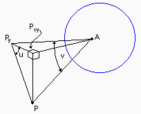
Py = projection of P onto the y-axis.
Pxy = projection of P onto the x-y plane.
u = angle subtended at Py by PxyP.
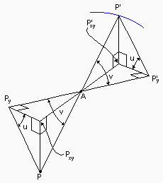
P' = projection of P through A to the surface of the
sphere (eye).
P' y = foot of perpendicular from P' to PyA extended.
P'xy = foot of perpendicular from P' to PxyA extended.
Thus angles u and v are as shown:
u = arctan(PxyP / PxyPy) = arctan(z/x)
v = arctan(PyP / PyA) = arctan([x2+z2]½/y)
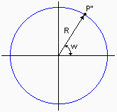
The two-dimesional representation of P' in polar co-ordinates, P'' = (R,w), is created by:R = v (v is in radians)
w = u
Thus, P'' = (R,w) is the two-dimensional image of P on the retina of the spherical eye.